Questions with solutions
Question 1NEET 2026, Q11
A rectangular wire loop of sides and with a small cut, is moving out of a region of uniform magnetic field of magnitude directed normal to the plane of the loop. The emf developed across the cut, if the velocity of the loop is , in a direction normal to the shorter side of the loop, will be:
- 1 volt
- 2 volt
- 3 volt
- 4 volt
Show answer and solution
Correct: option 1, volt
When the loop moves normal to its shorter side, the side that cuts the field lines is the shorter one, . The motional emf is .
Question 2NEET 2026 Re-exam, Q3
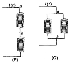
Two identical inductors are connected in two different configurations P and Q, where a time varying current is flowing, as shown in the figure. The induced emf between points and for configuration P is and that for configuration Q is . The ratio is:
[Neglect the effect of mutual inductance.]
- 11/4
- 21/2
- 31
- 42
Show answer and solution
Correct: option 4, 2
In P the points and are the two ends of one inductor carrying the full current, so . In Q the two identical inductors are in parallel between and , each carries , so . The ratio is 2, option (4).
Question 3NEET 2026 Re-exam, Q5
Consider a long solenoid of length and radius r. If n is the number of turns per unit length and is the permeability of free space, the inductance of the solenoid is:
- 1
- 2
- 3
- 4
Show answer and solution
Correct: option 1,
The field inside is . The flux through all turns is , and dividing by gives , option (1).
Question 4NEET 2026 Re-exam, Q32
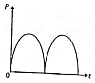
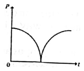
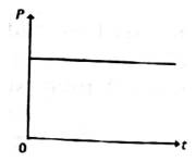
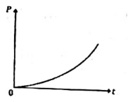
A conducting loop of finite resistance lies on the - plane. There is a constant magnetic field in the direction. The area of the loop varies with time , as in appropriate units. The figure that correctly indicates the qualitative behaviour of the power dissipated in the loop as a function of time is:
- 1
- 2
- 3
- 4
Show answer and solution
Correct: option 2
The flux is , so the induced emf has magnitude and the power dissipated is . It is largest at , falls to zero at and then rises again, which is the graph in option (2).
Question 5NEET 2025, Q11
AB is a part of an electrical circuit (see figure). The potential difference "", at the instant when current i = 2 A and is increasing at a rate of 1 amp / second is:

- 15 volt
- 26 volt
- 39 volt
- 410 volt
Show answer and solution
Correct: option 4, 10 volt
Go from A to B along the current. The potential falls by V across the inductor (the current is increasing), by 5 V across the cell (it is crossed from its positive to its negative plate), and by V across the resistor. So volt, option (4).
Question 6NEET 2024, Q19
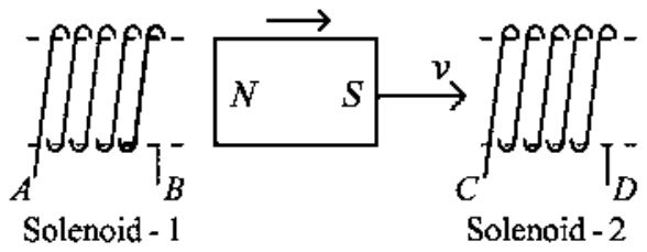
In the above diagram, a strong bar magnet is moving towards solenoid-2 from solenoid-1. The direction of induced current in solenoid-1 and that in solenoid-2, respectively, are through the directions:
- 1 and
- 2 and
- 3 and
- 4 and
Show answer and solution
Correct: option 2, and
By Lenz's law each solenoid opposes the change in flux through it. The north pole is moving away from solenoid-1, so the end of solenoid-1 facing the magnet becomes a south pole to attract it back. The south pole is approaching solenoid-2, so the end of solenoid-2 facing the magnet becomes a south pole to repel it. With the windings as drawn, these polarities need the current to flow along in solenoid-1 and along in solenoid-2, option (2).
Question 7NEET 2024, Q44
A sheet is placed on a horizontal surface in front of a strong magnetic pole. A force is needed to:
A. hold the sheet there if it is magnetic.
B. hold the sheet there if it is non-magnetic.
C. move the sheet away from the pole with uniform velocity if it is conducting.
D. move the sheet away from the pole with uniform velocity if it is both, non-conducting and non-polar.
Choose the correct statement(s) from the options given below:
- 1C only
- 2B and D only
- 3A and C only
- 4A, C and D only
Show answer and solution
Correct: option 3, A and C only
A is true: a magnetic sheet is pulled towards the pole, so a force is needed to hold it in place. B is false: a non-magnetic sheet feels no force from the pole. C is true: moving a conducting sheet through the changing field sets up eddy currents that oppose the motion, so a force is needed to keep it moving at uniform velocity. D is false: a non-conducting, non-polar sheet has neither eddy currents nor magnetic attraction. So A and C only, option (3).
Question 8NEET 2024 Re-exam, Q28
Let us consider two solenoids A and B, made from same magnetic material of relative permeability and equal area of cross-section. Length of A is twice that of B and the number of turns per unit length in A is half that of B. The ratio of self inductances of the two solenoids, is
- 11 : 2
- 22 : 1
- 38 : 1
- 41 : 8
Show answer and solution
Correct: option 1, 1 : 2
For a solenoid . The core and area are the same, so , that is 1 : 2.
Question 9NEET 2023, Q13
The magnetic energy stored in an inductor of inductance carrying a current of 2 A is:
- 1
- 2
- 3
- 4
Show answer and solution
Correct: option 4,
J , option (4).
Question 10NEET 2023 Manipur, Q49
An emf is generated by an ac generator having 100 turn coil, of loop area . The coil rotates at a speed of one revolution per second and placed in a uniform magnetic field of 0.05 T perpendicular to the axis of rotation of the coil. The maximum value of emf is
- 162.8 V
- 26.28 V
- 33.14 V
- 431.4 V
Show answer and solution
Correct: option 4, 31.4 V
Peak emf of a generator is , with . V.
Question 11NEET 2022, Q33
A square loop of side 1 m and resistance is placed in a magnetic field of 0.5 T. If the plane of loop is perpendicular to the direction of magnetic field, the magnetic flux through the loop is:
- 1zero weber
- 22 weber
- 30.5 weber
- 41 weber
Show answer and solution
Correct: option 3, 0.5 weber
With the plane of the loop perpendicular to the field, the field is along the area vector, so weber, option (3). The resistance plays no part.
Question 12NEET 2022, Q48
A big circular coil of 1000 turns and average radius 10 m is rotating about its horizontal diameter at . If the vertical component of earth's magnetic field at that place is T and electrical resistance of the coil is , then the maximum induced current in the coil will be:
- 12 A
- 20.25 A
- 31.5 A
- 41 A
Show answer and solution
Correct: option 4, 1 A
Maximum emf of a rotating coil is V. Maximum current A, option (4).
Question 13NEET 2022 Re-exam, Q46
The magnetic flux linked to a circular coil of radius is
Wb
The magnitude of induced emf in the coil at s is
- 1192 V
- 2108 V
- 3197 V
- 4150 V
Show answer and solution
Correct: option 1, 192 V
The induced emf has magnitude . At s this is V, option (1).
Question 14NEET 2021, Q36
Two conducting circular loops of radii and are placed in the same plane with their centres coinciding. If , the mutual inductance M between them will be directly proportional to:
- 1
- 2
- 3
- 4
Show answer and solution
Correct: option 4,
A current I in the large loop makes a field at its centre, which is nearly uniform over the small loop. The flux through the small loop is , so .
Question 15NEET 2020 Phase 2, Q94
The magnetic flux linked with a coil (in Wb) is given by the equation
The magnitude of induced emf in the coil at the fourth second will be
- 143 V
- 2108 V
- 310 V
- 433 V
Show answer and solution
Correct: option 1, 43 V
By Faraday's law the magnitude of the induced emf is . At this is .
Question 16NEET 2020 Phase 2, Q133
A wheel with 20 metallic spokes each 1 m long is rotated with a speed of 120 rpm in a plane perpendicular to a magnetic field of 0.4 G. The induced emf between the axle and rim of the wheel will be, ()
- 1
- 2
- 3
- 4
Show answer and solution
Correct: option 4,
Each spoke is a rod rotating about one end, so the emf across it is . Here and , so . The spokes are in parallel between axle and rim, so the number of spokes does not change the emf.
Question 17NEET 2019, Q6
In which of the following devices, the eddy current effect is not used?
- 1induction furnace
- 2magnetic braking in train
- 3electromagnet
- 4electric heater
Show answer and solution
Correct: option 3 or 4
The answer key accepts options 3 and 4.
An induction furnace heats metal by eddy currents and magnetic braking in trains uses the drag of eddy currents. An electromagnet works by the magnetic effect of the current in its coil, and an electric heater by Joule heating in a resistance wire; neither uses eddy currents. The official final key accepts both option (3) and option (4).
Question 18NEET 2019, Q41
A 800 turn coil of effective area is kept perpendicular to a magnetic field T. When the plane of the coil is rotated by around any of its coplanar axis in 0.1 s, the emf induced in the coil will be:
- 12 V
- 20.2 V
- 3 V
- 40.02 V
Show answer and solution
Correct: option 4, 0.02 V
The flux through the coil changes from to zero. V.
Question 19NEET 2019 Odisha, Q11
A cycle wheel of radius 0.5 m is rotated with constant angular velocity of 10 rad/s in a region of magnetic field of 0.1 T which is perpendicular to the plane of the wheel. The EMF generated between its centre and the rim is,
- 10.5 V
- 2zero
- 30.25 V
- 40.125 V
Show answer and solution
Correct: option 4, 0.125 V
Each spoke is a rod rotating about one end, so the EMF between centre and rim is V.
Question 20NEET 2018, Q21
The magnetic potential energy stored in a certain inductor is 25 mJ, when the current in the inductor is 60 mA. This inductor is of inductance
- 11.389 H
- 2138.88 H
- 30.138 H
- 413.89 H
Show answer and solution
Correct: option 4, 13.89 H
, so .
Question 21NEET 2017, Q38
A long solenoid of diameter 0.1 m has turns per meter. At the centre of the solenoid, a coil of 100 turns and radius 0.01 m is placed with its axis coinciding with the solenoid axis. The current in the solenoid reduces at a constant rate to 0 A from 4 A in 0.05 s. If the resistance of the coil is , the total charge flowing through the coil during this time is:
- 1C
- 2C
- 3C
- 4C
Show answer and solution
Correct: option 3, C
The charge that flows depends only on the change in flux: . The field inside the solenoid changes by T. The coil area is . So C C.
Question 22NEET 2016 Phase 1, Q42
A long solenoid has 1000 turns. When a current of 4A flows through it, the magnetic flux linked with each turn of the solenoid is Wb. The self-inductance of the solenoid is:
- 14 H
- 23 H
- 32 H
- 41 H
Show answer and solution
Correct: option 4, 1 H
Total flux linkage is Wb. H.
Question 23NEET 2016 Phase 2, Q31
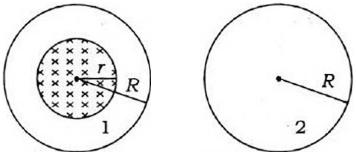
A uniform magnetic field is restricted within a region of radius . The magnetic field changes with time at a rate . Loop 1 of radius encloses the region and loop 2 of radius is outside the region of magnetic field as shown in the figure below. Then the e.m.f. generated is
- 1zero in loop 1 and zero in loop 2
- 2 in loop 1 and in loop 2
- 3 in loop 1 and zero in loop 2
- 4 in loop 1 and zero in loop 2
Show answer and solution
Correct: option 4, in loop 1 and zero in loop 2
The induced e.m.f. is , where is the flux through the loop. Loop 1 encloses the whole field region, whose area is (not , because there is no field between and ), so its e.m.f. is . Loop 2 lies wholly outside the field, so its flux is always zero and no e.m.f. is induced. That is option (4).
Question 24AIPMT 2015, Q179
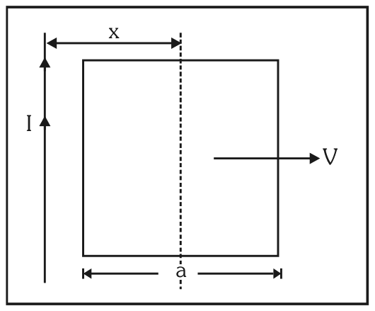
A conducting square frame of side 'a' and a long straight wire carrying current I are located in the same plane as shown in the figure. The frame moves to the right with a constant velocity 'V'. The emf induced in the frame will be proportional to:
- 1
- 2
- 3
- 4
Show answer and solution
Correct: option 3,
The centre of the frame is at distance x from the wire, so the sides parallel to the wire are at and . Each has a motional emf with , and the two oppose each other round the loop (the other two sides give none). Net emf , so it is proportional to , option (3).
Question 25AIPMT 2015 Re-test, Q138
An electron moves on a straight line path XY as shown. The abcd is a coil adjacent to the path of electron. What will be the direction of current, if any, induced in the coil?
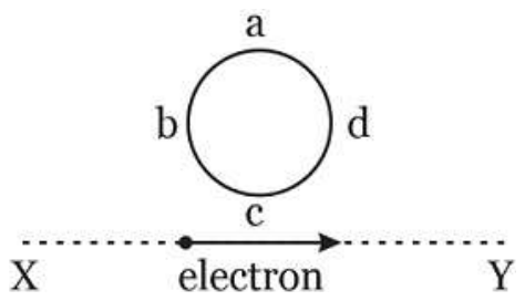
- 1No current induced
- 2abcd
- 3adcb
- 4The current will reverse its direction as the electron goes past the coil
Show answer and solution
Correct: option 4, The current will reverse its direction as the electron goes past the coil
The moving electron is a current along the line, so it produces a magnetic field through the coil. While the electron approaches, the flux through the coil grows; after it passes, the flux falls. By Lenz's law the induced current opposes the change each time, so it flows one way during the approach and the opposite way afterwards: the current reverses as the electron goes past the coil.
Question 26AIPMT 2014, Q123
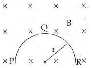
A thin semicircular conducting ring (PQR) of radius 'r' is falling with its plane vertical in a horizontal magnetic field B, as shown in figure. The potential difference developed across the ring when its speed is v, is:
- 1 and R is at higher potential
- 2Zero
- 3 and P is at higher potential
- 4 and R is at higher potential
Show answer and solution
Correct: option 1, and R is at higher potential
The motional emf of a bent conductor equals that of the straight line joining its ends. Here that line is the diameter PR of length , which is horizontal and moves down at speed v at right angles to B, so the emf is . With B into the page and the velocity downward, the force pushes positive charge towards R, so R is at the higher potential: option (1).
Question 27NEET 2013, Q143
A wire loop is rotated in a magnetic field. The frequency of change of direction of the induced e.m.f. is:
- 1twice per revolution
- 2four times per revolution
- 3six times per revolution
- 4once per revolution
Show answer and solution
Correct: option 1, twice per revolution
The induced e.m.f. varies as , which passes through zero and reverses sign twice in every full turn of the loop. So its direction changes twice per revolution.
Question 28NEET 2013 Karnataka, Q154
A current of 2.5 A flows through a coil of inductance 5 H. The magnetic flux linked with the coil is:
- 10.5 Wb
- 212.5 Wb
- 3Zero
- 42 Wb
Show answer and solution
Correct: option 2, 12.5 Wb
Flux linked with a coil is .
Question 29AIPMT 2012 Prelims, Q8
A coil of resistance is placed in a magnetic field. If the magnetic flux (wb) linked with the coil varies with time t (sec) as . The current in the coil at t = 2 sec is:
- 10.5 A
- 20.1 A
- 32 A
- 41 A
Show answer and solution
Correct: option 1, 0.5 A
The induced emf has magnitude , which is 200 V at t = 2 s. The current is .
Question 30AIPMT 2012 Prelims, Q17
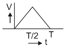
The current (I) in the inductance is varying with time according to the plot shown in figure.
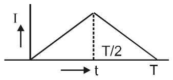
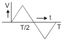
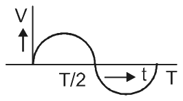
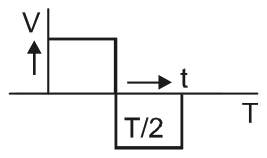
Which one of the following is the correct variation of voltage with time in the coil?
- 1
- 2
- 3
- 4
Show answer and solution
Correct: option 4
The voltage across an inductor has magnitude , so it follows the slope of the I-t graph. The current rises at a steady rate up to T/2 and then falls at the same steady rate, so the voltage is constant with one sign for the first half and constant with the opposite sign for the second half. That rectangular graph is option (4).
Question 31AIPMT 2012 Mains, Q21
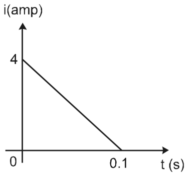
In a coil of resistance , the induced current developed by changing magnetic flux through it, is shown in figure as a function of time. The magnitude of change in flux through the coil in Weber is:
- 18
- 22
- 36
- 44
Show answer and solution
Correct: option 2, 2
The induced current is , so the charge that flows is . The charge is the area under the i-t graph, a triangle: C. Therefore Wb.
Question 32AIPMT 2011 Prelims, Q199
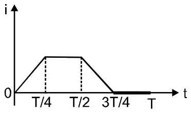
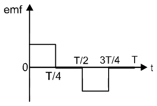
The current i in a coil varies with time as shown in the figure. The variation of induced emf with time would be:
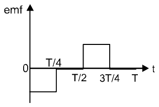
- 1
- 2
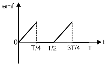
- 3
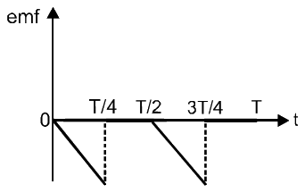
- 4
Show answer and solution
Correct: option 1
The induced emf is . From 0 to T/4 the current rises at a steady rate, so the emf is constant and negative. From T/4 to T/2 the current is constant, so the emf is zero. From T/2 to 3T/4 the current falls at a steady rate, so the emf is constant and positive, and after 3T/4 it is zero again. Graph (1) shows exactly this.
Question 33AIPMT 2010 Prelims, Q19
A conducting circular loop is placed in a uniform magnetic field, B = 0.025 T with its plane perpendicular to the loop. The radius of the loop is made to shrink at a constant rate of 1 mm s. The induced emf when the radius is 2 cm, is
- 1
- 2
- 3
- 4
Show answer and solution
Correct: option 2,
With the field perpendicular to the plane of the loop the flux is , so the emf has magnitude . Putting in the values, V, which is .
Question 34AIPMT 2009 Prelims, Q23
A rectangular, a square, a circular and an elliptical loop, all in the (x - y) plane, are moving out of a uniform magnetic field with a constant velocity, . The magnetic field is directed along the negative z axis direction. The induced emf, during the passage of these loops, out of the field region, will not remain constant for:
- 1the circular and the elliptical loops.
- 2only the elliptical loop.
- 3any of the four loops.
- 4the rectangular, circular and elliptical loops.
Show answer and solution
Correct: option 3, any of the four loops.
The emf is , where is the length of the loop cut by the edge of the field. For a rectangular or square loop with sides along the axes this length stays the same while the loop leaves, so the emf is constant; for a circular or elliptical loop the length changes continuously, so the emf varies. This working points to option (1). The answer key available for this paper marks option (3), and that is the answer recorded here; the working above does not support it.
Question 35AIPMT 2009 Prelims, Q42
A conducting circular loop is placed in a uniform magnetic field 0.04 T with its plane perpendicular to the magnetic field. The radius of the loop starts shrinking at 2 mm/s. The induced emf in the loop when the radius is 2 cm is:
- 1
- 2
- 3
- 4
Show answer and solution
Correct: option 4,
The flux is , so the emf has magnitude V, that is .
Question 36AIPMT 2008 Prelims, Q35
A circular disc of radius 0.2 meter is placed in a uniform magnetic field of induction in such a way that its axis makes an angle of with . The magnetic flux linked with the disc is
- 10.01 Wb
- 20.02 Wb
- 30.06 Wb
- 40.08 Wb
Show answer and solution
Correct: option 2, 0.02 Wb
The flux is , where is the angle between the field and the axis (the normal) of the disc. Wb.
Question 37AIPMT 2008 Prelims, Q38
A long solenoid has 500 turns. When a current of 2 ampere is passed through it, the resulting magnetic flux linked with each turn of the solenoid is Wb. The self-inductance of the solenoid is
- 14.0 henry
- 22.5 henry
- 32.0 henry
- 41.0 henry
Show answer and solution
Correct: option 4, 1.0 henry
The total flux linkage is . So henry.
Question 38AIPMT 2006 Prelims, Q24
Two coils of self inductances 2 mH and 8 mH are placed so close together that the effective flux in one coil is completely linked with the other. The mutual inductance between these coils is:
- 110 mH
- 26 mH
- 34 mH
- 416 mH
Show answer and solution
Correct: option 3, 4 mH
With complete flux linkage the coupling coefficient is 1, so .
Question 39AIPMT 2005 Prelims, Q21
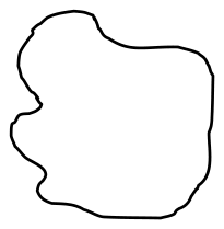
As a result of change in the magnetic flux linked to the closed loop shown in the figure, an e.m.f. V volt is induced in the loop. The work done (joules) in taking a charge Q coulomb once along the loop is
- 1QV
- 2QV/2
- 32QV
- 4Zero
Show answer and solution
Correct: option 1, QV
The induced electric field is non-conservative, and the induced e.m.f. is by definition the work done per unit charge taken once round the loop. For a charge Q the work is therefore QV.
Question 40AIPMT 2004 Prelims, Q23
The magnetic flux through a circuit of resistance R changes by an amount in a time . Then the total quantity of electric charges Q that passes any point in the circuit during the time is represented by:-
- 1
- 2
- 3
- 4
Show answer and solution
Correct: option 1,
The induced emf is , so the current is . The charge that flows is , independent of the time taken.
Question 41AIPMT 2004 Prelims, Q45
A coil of 40 henry inductance is connected in series with a resistance of 8 ohm and the combination is joined to the terminals of a 2 volt battery. The time constant of the circuit is:-
- 11/5 seconds
- 240 seconds
- 320 seconds
- 45 seconds
Show answer and solution
Correct: option 4, 5 seconds
The time constant of an L-R circuit is seconds. It does not depend on the battery voltage.
Question 42AIPMT 2001 Prelims, Q35
For a coil having L = 2 mH, current flow through it is then the time at which emf become zero:
- 12 s
- 21 s
- 34 s
- 43 s
Show answer and solution
Correct: option 1, 2 s
The induced emf is , and . This is zero (for ) when s.
Question 43AIPMT 1999 Prelims, Q11
Initially plane of coil is parallel to the uniform magnetic field B. In time it makes to perpendicular to the magnetic field, then charge flows in depends on this time as -
- 1
- 2
- 3
- 4
Show answer and solution
Correct: option 3,
The charge that flows is , the change of flux divided by the resistance of the circuit. The flux changes from 0 to whatever the time taken, so the charge does not depend on , that is .
Question 44AIPMT 1999 Prelims, Q14
For a inductor coil L = 0.04 H, then workdone by source to establish a current of 5A in it is -
- 10.5 J
- 21.00 J
- 3100 J
- 420 J
Show answer and solution
Correct: option 2, 1.00 J
The key used for this paper gives 1.00 J, which is J. Note that the energy stored in the magnetic field of the inductor is J, and the work done against the back emf of an ideal inductor equals this stored energy, so on the standard treatment the answer would be 0.5 J (option 1). The keyed answer is kept here as the source gives it.
Question 45AIPMT 1998 Prelims, Q23
Two coil have a mutual inductance 0.005 H. The current changes in first coil according to equation where and rad/sec. The maximum value of emf in second coil is:
- 1
- 2
- 3
- 4
Show answer and solution
Correct: option 4,
The induced emf is in magnitude, so its maximum is volt.