Questions with solutions
Question 1NEET 2026, Q7
An ac circuit contains a resistance of , a capacitor of and an inductor of connected in series. The resonance frequency of the circuit is approximately:
- 1
- 2
- 3
- 4
Show answer and solution
Correct: option 3,
The resonance frequency does not depend on the resistance: .
Question 2NEET 2026, Q33
The peak value of an alternating current is and frequency is . How long will the current, starting from zero, take to reach the peak value?
- 1
- 2
- 3
- 4
Show answer and solution
Correct: option 1,
The period is . A sinusoidal current rises from zero to its peak in a quarter of a period: .
Question 3NEET 2026 Re-exam, Q30
An ac voltage Volt is applied to a series LCR circuit. Then the current amplitude in this circuit is:
(Given: mH, , )
- 12.2 A
- 25.5 A
- 311.0 A
- 422.0 A
Show answer and solution
Correct: option 1, 2.2 A
Here . and . The reactances cancel (resonance), so the impedance is just and the current amplitude is A, option (1).
Question 4NEET 2025, Q16
To an ac power supply of 220 V at 50 Hz, a resistor of , a capacitor of reactance and an inductor of reactance are connected in series. The corresponding current in the circuit and the phase angle between the current and the voltage is, respectively -
- 17.8 A and
- 27.8 A and
- 315.6 A and
- 415.6 A and
Show answer and solution
Correct: option 2, 7.8 A and
The net reactance is , so the impedance is . The current is A, and gives . That is option (2).
Question 5NEET 2024, Q20
In an ideal transformer, the turns ratio is . The ratio is equal to (the symbols carry their usual meaning):
- 11 : 4
- 21 : 2
- 32 : 1
- 41 : 1
Show answer and solution
Correct: option 3, 2 : 1
For an ideal transformer . So , option (3).
Question 6NEET 2024, Q38
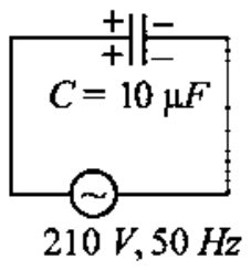
A capacitor is connected to a 210 V, 50 Hz source as shown in figure. The peak current in the circuit is nearly ():
- 1
- 2
- 3
- 4
Show answer and solution
Correct: option 3,
210 V is the rms voltage. The rms current is A. The peak current is A, option (3).
Question 7NEET 2024 Re-exam, Q10
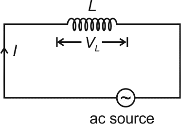
In the circuit shown below, the inductance is connected to an ac source. The current flowing in the circuit is . The voltage drop () across is
- 1
- 2
- 3
- 4
Show answer and solution
Correct: option 4,
The voltage across an inductor is . Differentiating gives : the amplitude is times the reactance , and the voltage leads the current by .
Question 8NEET 2024 Re-exam, Q14
A step up transformer is connected to an ac mains supply of 220 V to operate at 11000 V, 88 watt. The current in the secondary circuit, ignoring the power loss in the transformer, is
- 18 mA
- 24 mA
- 30.4 A
- 44 A
Show answer and solution
Correct: option 1, 8 mA
The secondary delivers 88 W at 11000 V, so A = 8 mA. (0.4 A is the primary current, .)
Question 9NEET 2024 Re-exam, Q49
The amplitude of the charge oscillating in a circuit decreases exponentially as , where is the charge at s. The time at which charge amplitude decreases to is nearly:
[Given that , mH, ]
- 119.01 ms
- 211.09 ms
- 319.01 s
- 411.09 s
Show answer and solution
Correct: option 2, 11.09 ms
Setting gives , so s = 11.09 ms.
Question 10NEET 2023, Q8
A 12 V, 60 W lamp is connected to the secondary of a step down transformer, whose primary is connected to ac mains of 220 V. Assuming the transformer to be ideal, what is the current in the primary winding?
- 10.27 A
- 22.7 A
- 33.7 A
- 40.37 A
Show answer and solution
Correct: option 1, 0.27 A
In an ideal transformer the input power equals the output power, so W. Then A, option (1).
Question 11NEET 2023, Q29
In a series circuit, the inductance is 10 mH, capacitance is and resistance is . The frequency at which resonance occurs is:
- 115.9 rad/s
- 215.9 kHz
- 31.59 rad/s
- 41.59 kHz
Show answer and solution
Correct: option 4, 1.59 kHz
. The frequency is Hz kHz, option (4). The resistance does not affect the resonant frequency.
Question 12NEET 2023, Q37
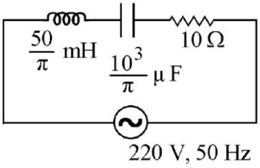
The net impedance of circuit (as shown in figure) will be:
- 1
- 2
- 3
- 4
Show answer and solution
Correct: option 3,
. and . So , option (3).
Question 13NEET 2023 Manipur, Q8
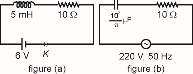
If and are the impedances of the given circuits (a) and (b) as shown in figures, then choose the correct option.
- 1
- 2
- 3
- 4
Show answer and solution
Correct: option 3,
Circuit (a) has a 6 V dc source, and for steady dc an inductor offers no reactance, so . In circuit (b), , so . Hence .
Question 14NEET 2023 Manipur, Q13
The maximum power is dissipated for an ac in a/an
- 1Inductive circuit
- 2Capacitive circuit
- 3Resistive circuit
- 4LC circuit
Show answer and solution
Correct: option 3, Resistive circuit
Average power is . In a purely resistive circuit the current and voltage are in phase, so and the power is maximum. In purely inductive, capacitive or LC circuits the phase difference is , and no power is dissipated.
Question 15NEET 2023 Manipur, Q31
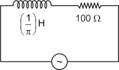
An ac source is connected in the given circuit. The value of will be
- 1
- 2
- 3
- 4
Show answer and solution
Correct: option 2,
From the source, , so . In a series LR circuit the voltage leads the current by with , so .
Question 16NEET 2023 Manipur, Q40
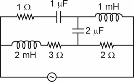
For very high frequencies, the effective impedance of the circuit (shown in the figure) will be
- 1
- 2
- 3
- 4
Show answer and solution
Correct: option 2,
At very high frequency , so each capacitor acts as a plain wire, and , so each inductor acts as a break. The 1 mH branch and the 2 mH, branch are therefore open. Current flows through the resistor, the two capacitors and then the resistor, so .
Question 17NEET 2022, Q23
The peak voltage of the ac source is equal to:
- 1 times the rms value of the ac source
- 2the value of voltage supplied to the circuit
- 3the rms value of the ac source
- 4 times the rms value of the ac source
Show answer and solution
Correct: option 4, times the rms value of the ac source
For a sinusoidal supply , so the peak value is , option (4).
Question 18NEET 2022, Q40
A series LCR circuit with inductance 10 H, capacitance , resistance is connected to an ac source of voltage, volt. If the resonant frequency of the LCR circuit is and the frequency of the ac source is , then:
- 1 Hz; Hz
- 2 Hz
- 3 Hz
- 4 Hz, Hz
Show answer and solution
Correct: option 3, Hz
The source has rad/s, so Hz. The resonant angular frequency is rad/s, so Hz too. Hence Hz, option (3).
Question 19NEET 2022 Re-exam, Q14
Given below are two statements
Statement I: In an ac circuit, the current through a capacitor leads the voltage across it.
Statement II: In a.c. circuit containing pure capacitance only, the phase difference between the current and the voltage is .
In the light of the above statements, choose the most appropriate answer from the options given below
- 1Statement I is incorrect but Statement II is correct
- 2Both Statement I and Statement II are correct
- 3Both Statement I and Statement II are incorrect
- 4Statement I is correct but Statement II is incorrect
Show answer and solution
Correct: option 4, Statement I is correct but Statement II is incorrect
In a purely capacitive ac circuit the current leads the voltage, so Statement I is correct. The lead is a quarter of a cycle, a phase difference of and not , so Statement II is incorrect. Option (4).
Question 20NEET 2022 Re-exam, Q21
An inductor of inductance 2 mH is connected to a 220 V, 50 Hz a.c. source. Let the inductive reactance in the circuit is . If a 220 V dc source replace the ac source in the circuit, then the inductive reactance in the circuit is . and respectively are:
- 1, infinity
- 2, zero
- 3, infinity
- 4, zero
Show answer and solution
Correct: option 4, , zero
Inductive reactance is . For the ac source . For dc the frequency is zero, so . Option (4).
Question 21NEET 2022 Re-exam, Q34
A standard filament lamp consumes 100 W when connected to 200 V ac mains supply. The peak current through the bulb will be:
- 12 A
- 20.707 A
- 31 A
- 41.414 A
Show answer and solution
Correct: option 2, 0.707 A
The rms current is A. The peak current is A, option (2).
Question 22NEET 2021, Q31
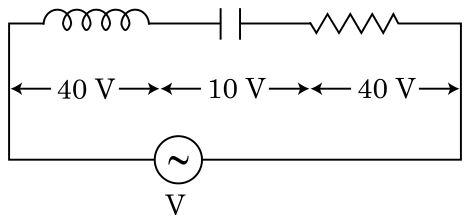
An inductor of inductance L, a capacitor of capacitance C and a resistor of resistance 'R' are connected in series to an ac source of potential difference 'V' volts as shown in figure.
Potential difference across L, C and R is 40 V, 10 V and 40 V, respectively. The amplitude of current flowing through LCR series circuit is A. The impedance of the circuit is:
- 1
- 2
- 3
- 4
Show answer and solution
Correct: option 4,
The source voltage is V (rms). The rms current is A. Impedance .
Question 23NEET 2021, Q40
A series LCR circuit containing 5.0 H inductor, 80 F capacitor and 40 resistor is connected to 230 V variable frequency ac source. The angular frequencies of the source at which power transferred to the circuit is half the power at the resonant angular frequency are likely to be:
- 125 rad/s and 75 rad/s
- 250 rad/s and 25 rad/s
- 346 rad/s and 54 rad/s
- 442 rad/s and 58 rad/s
Show answer and solution
Correct: option 3, 46 rad/s and 54 rad/s
Resonant angular frequency: rad/s. The half-power points lie at , that is 46 rad/s and 54 rad/s.
Question 24NEET 2021, Q50
A step down transformer connected to an ac mains supply of 220 V is made to operate at 11 V, 44 W lamp. Ignoring power losses in the transformer, what is the current in the primary circuit?
- 10.2 A
- 20.4 A
- 32 A
- 44 A
Show answer and solution
Correct: option 1, 0.2 A
With no losses, input power = output power: W. So A.
Question 25NEET 2020, Q162
A series LCR circuit is connected to an ac voltage source. When L is removed from the circuit, the phase difference between current and voltage is . If instead C is removed from the circuit, the phase difference is again between current and voltage. The power factor of the circuit is:
- 1zero
- 20.5
- 31.0
- 4
Show answer and solution
Correct: option 3, 1.0
With L removed (an RC circuit) ; with C removed (an RL circuit) . So , the full LCR circuit is at resonance and its impedance is just R. The power factor is .
Question 26NEET 2020, Q163
A capacitor is connected to a 200 V, 50 Hz ac supply. The rms value of the current in the circuit is, nearly:
- 11.7 A
- 22.05 A
- 32.5 A
- 425.1 A
Show answer and solution
Correct: option 3, 2.5 A
The capacitive reactance is , so , nearly 2.5 A.
Question 27NEET 2020 Phase 2, Q106
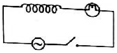
A light bulb and an inductor coil are connected to an ac source through a key as shown in the figure below. The key is closed and after sometime an iron rod is inserted into the interior of the inductor. The glow of the light bulb
- 1remains unchanged
- 2will fluctuate
- 3increases
- 4decreases
Show answer and solution
Correct: option 4, decreases
Putting an iron rod inside the coil raises its inductance , so its reactance goes up. The impedance of the series circuit rises, the current falls, and the bulb glows less brightly.
Question 28NEET 2019 Odisha, Q10
A circuit when connected to an AC source of 12 V gives a current of 0.2 A. The same circuit when connected to a DC source of 12 V, gives a current of 0.4 A. The circuit is
- 1series LC
- 2series LCR
- 3series LR
- 4series RC
Show answer and solution
Correct: option 3, series LR
A steady DC current flows, so there is no capacitor in series (a capacitor blocks DC). The current is smaller on AC, so the impedance is larger than the resistance, which needs an inductor. The circuit is a series LR circuit.
Question 29NEET 2019 Odisha, Q32
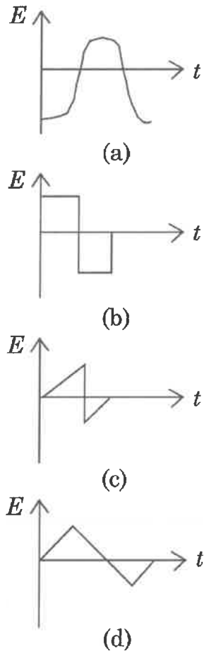
The variation of EMF with time for four types of generators are shown in the figures. Which amongst them can be called AC?
- 1(a) and (b)
- 2only (a)
- 3(a) and (d)
- 4(a), (b), (c), (d)
Show answer and solution
Correct: option 4, (a), (b), (c), (d)
An EMF is alternating if its direction (sign) reverses periodically; the wave does not have to be a sine curve. In all four graphs E is positive for part of the cycle and negative for the rest, so all of (a), (b), (c) and (d) are AC.
Question 30NEET 2018, Q28
An inductor 20 mH, a capacitor and a resistor are connected in series across a source of emf, V = 10 sin 314 t. The power loss in the circuit is
- 12.74 W
- 20.43 W
- 30.79 W
- 41.13 W
Show answer and solution
Correct: option 3, 0.79 W
and , so . Power is lost only in the resistor: .
Question 31NEET 2016 Phase 1, Q40
An inductor 20 mH, a capacitor and a resistor are connected in series across a source of emf . The power loss in A.C. circuit is:
- 10.51 W
- 20.67 W
- 30.76 W
- 40.89 W
Show answer and solution
Correct: option 1, 0.51 W
and , so . Power W. The nearest option, and the keyed answer, is 0.51 W.
Question 32NEET 2016 Phase 1, Q43
A small signal voltage is applied across an ideal capacitor C:
- 1Current I(t), lags voltage V(t) by 90°.
- 2Over a full cycle the capacitor C does not consume any energy from the voltage source.
- 3Current I(t) is in phase with voltage V(t).
- 4Current I(t) leads voltage V(t) by 180°.
Show answer and solution
Correct: option 2, Over a full cycle the capacitor C does not consume any energy from the voltage source.
In a pure capacitor the current leads the voltage by 90°, so the average power is zero. Energy stored in one quarter cycle is returned in the next, so over a full cycle the capacitor consumes no energy.
Question 33NEET 2016 Phase 2, Q30
Which of the following combinations should be selected for better tuning of an L-C-R circuit used for communication?
- 1, H, F
- 2, H, F
- 3, H, F
- 4, H, F
Show answer and solution
Correct: option 3, , H, F
Sharper tuning needs a larger quality factor , which calls for small , large and small . Option (3) has the smallest (15 ), the largest (3.5 H) and the smallest (30 F), so it gives the highest and the best tuning.
Question 34NEET 2016 Phase 2, Q32
The potential differences across the resistance, capacitance and inductance are 80 V, 40 V and 100 V respectively in an L-C-R circuit. The power factor of this circuit is
- 10.4
- 20.5
- 30.8
- 41.0
Show answer and solution
Correct: option 3, 0.8
The net voltage is V. Power factor , option (3).
Question 35AIPMT 2015, Q168
A resistance 'R' draws power 'P' when connected to an AC source. If an inductance is now placed in series with the resistance, such that the impedance of the circuit becomes 'Z', the power drawn will be:
- 1
- 2
- 3
- 4
Show answer and solution
Correct: option 4,
With the resistance alone, , where V is the rms voltage. With the inductance in series the rms current is and power is dissipated only in R: . This is option (4).
Question 36AIPMT 2015 Re-test, Q162
A series R-C circuit is connected to an alternating voltage source. Consider two situations:
(a) When capacitor is air filled.
(b) When capacitor is mica filled.
Current through resistor is and voltage across capacitor is V then:
- 1
- 2
- 3
- 4
Show answer and solution
Correct: option 3,
Mica is a dielectric, so it raises the capacitance and lowers the reactance . The impedance falls, so the current rises () and a larger share of the source voltage appears across R. The capacitor voltage therefore falls when C increases: .
Question 37AIPMT 2014, Q121
A transformer having efficiency of 90% is working on 200 V and 3 kW power supply. If the current in the secondary coil is 6 A, the voltage across the secondary coil and the current in the primary coil respectively are:
- 1600 V, 15 A
- 2300 V, 15 A
- 3450 V, 15 A
- 4450 V, 13.5 A
Show answer and solution
Correct: option 3, 450 V, 15 A
Primary current . Output power , so the secondary voltage is . That is option (3).
Question 38NEET 2013, Q138
A coil of self-inductance L is connected in series with a bulb B and an AC source. Brightness of the bulb decreases when:
- 1number of turns in the coil is reduced.
- 2a capacitance of reactance is included in the same circuit.
- 3an iron rod is inserted in the coil.
- 4frequency of the AC source is decreased.
Show answer and solution
Correct: option 3, an iron rod is inserted in the coil.
The bulb dims when the impedance rises. An iron rod increases the inductance , so the reactance and the impedance go up and the current falls. Fewer turns or a lower frequency reduce the reactance, and a capacitor with cancels it, so each of those makes the bulb brighter.
Question 39NEET 2013 Karnataka, Q143
The primary of a transformer when connected to dc battery of 10 Volt draws a current of 1 mA. The number of turns of the primary and secondary windings are 50 and 100 respectively. The voltage in the secondary and the current drawn by the circuit in the secondary are respectively:
- 120 V and 2.0 mA
- 210 V and 0.5 mA
- 3Zero volt and therefore no current
- 420 V and 0.5 mA
Show answer and solution
Correct: option 3, Zero volt and therefore no current
A transformer works by mutual induction, which needs a changing flux. A steady dc current in the primary gives a constant flux, so no emf is induced in the secondary: zero volt and no current.
Question 40AIPMT 2012 Prelims, Q15
In an electrical circuit R, L, C and an a.c. voltage source are all connected in series. When L is removed from the circuit, the phase difference between the voltage and the current in the circuit is . If instead, C is removed from the circuit, the phase difference is again . The power factor of the circuit is:
- 11/2
- 2
- 31
- 4
Show answer and solution
Correct: option 3, 1
Without L the circuit is RC, so . Without C it is RL, so . Hence : the full circuit is at resonance, its impedance is just R, and the power factor .
Question 41AIPMT 2012 Mains, Q20
The instantaneous values of alternating current and voltages in a circuit are given as
ampere
Volt
The average power in Watts consumed in the circuit is:
- 1
- 2
- 3
- 4
Show answer and solution
Correct: option 4,
Average power is . The peak values are each , so the rms values are each , and the phase difference is with . Hence W.
Question 42AIPMT 2011 Prelims, Q175
A ac voltage is applied to a resistance R and an inductor L in series. If R and the inductive reactance are both equal to , the phase difference between the applied voltage and the current in the circuit is:
- 1
- 2
- 3
- 4zero
Show answer and solution
Correct: option 2,
For a series LR circuit , so .
Question 43AIPMT 2011 Prelims, Q181
In an ac circuit an alternating voltage volts is connected to a capacitor of capacity 1 F. The r.m.s. value of the current in the circuit is:
- 110 mA
- 2100 mA
- 3200 mA
- 420 mA
Show answer and solution
Correct: option 4, 20 mA
V and . The capacitive reactance is . So A mA.
Question 44AIPMT 2011 Mains, Q97
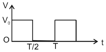
The r.m.s. value of potential difference V shown in the figure is:
- 1
- 2
- 3
- 4
Show answer and solution
Correct: option 2,
In each period T the voltage is for the first half and zero for the second half. The mean of over a period is therefore , and its square root gives .
Question 45AIPMT 2011 Mains, Q98
A coil has resistance 30 ohm and inductive reactance 20 Ohm at 50 Hz frequency. If an ac source, of 200 volt, 100 Hz, is connected across the coil, the current in the coil will be:
- 14.0 A
- 28.0 A
- 3 A
- 42.0 A
Show answer and solution
Correct: option 1, 4.0 A
Inductive reactance is proportional to frequency, so at 100 Hz it doubles to 40 ohm. The impedance is ohm, and the current is A.
Question 46AIPMT 2010 Mains, Q21
A condenser of capacity C is charged to a potential difference of . The plates of the condenser are then connected to an ideal inductor of inductance L. The current through the inductor when the potential difference across the condenser reduces to is
- 1
- 2
- 3
- 4
Show answer and solution
Correct: option 4,
With an ideal inductor no energy is lost, so the energy that leaves the condenser is stored in the inductor: . This gives .
Question 47AIPMT 2010 Prelims, Q38
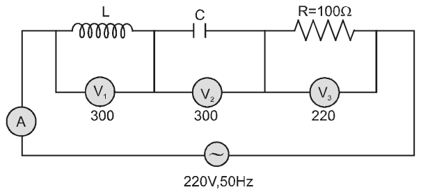
In the given circuit the reading of voltmeter and are 300 volts each. The reading of the voltmeter and ammeter A are respectively
- 1150 V, 2.2 A
- 2220 V, 2.2 A
- 3220 V, 2.0 A
- 4100 V, 2.0 A
Show answer and solution
Correct: option 2, 220 V, 2.2 A
The voltages across L and C are equal in size and opposite in phase, so they cancel and the circuit is at resonance. The whole supply voltage then appears across the resistor, so reads 220 V, and the impedance is just R. The current is A.
Question 48AIPMT 2010 Prelims, Q39
A 220 volt input is supplied to a transformer. The output circuit draws a current of 2.0 ampere at 440 volts. If the efficiency of the transformer is 80% the current drawn by the primary windings of the transformer is
- 13.6 ampere
- 22.8 ampere
- 32.5 ampere
- 45.0 ampere
Show answer and solution
Correct: option 4, 5.0 ampere
The output power is W. With 80% efficiency the input power is W. The primary current is therefore A.
Question 49AIPMT 2009 Prelims, Q25
Power dissipated in an LCR series circuit connected to an a.c source of emf is:
- 1
- 2
- 3
- 4
Show answer and solution
Correct: option 4,
The impedance is , the current is and power is dissipated only in the resistance. So .
Question 50AIPMT 2008 Prelims, Q39
In an a.c. circuit the e.m.f. (e) and the current (i) at any instant are given respectively by
The average power in the circuit over one cycle of a.c. is
- 1
- 2
- 3
- 4
Show answer and solution
Correct: option 4,
Average power is , where is the phase difference between emf and current. With and this is .
Question 51AIPMT 2007 Prelims, Q185
The primary and secondary coils of a transformer have 50 and 1500 turns respectively. If the magnetic flux linked with the primary coil is given by , where is in webers, t is time in seconds and is a constant, the output voltage across the secondary coil is
- 130 volts
- 290 volts
- 3120 volts
- 4220 volts
Show answer and solution
Correct: option 3, 120 volts
The emf in the primary is V. The voltages are in the ratio of the turns, so volts, option (3).
Question 52AIPMT 2007 Prelims, Q186
What is the value of inductance L for which the current is a maximum in a series LCR circuit with and ?
- 110 mH
- 2100 mH
- 31 mH
- 4cannot be calculated unless R is known
Show answer and solution
Correct: option 2, 100 mH
The current is greatest at resonance, where . So H mH, option (2). The resistance does not affect the resonance condition.
Question 53AIPMT 2007 Prelims, Q187
A transformer is used to light a 100W and 110V lamp from a 220V mains. If the main current is 0.5A, the efficiency of the transformer is approximately
- 110%
- 230%
- 350%
- 490%
Show answer and solution
Correct: option 4, 90%
Input power from the mains is W and the output power delivered to the lamp is 100 W. Efficiency , which is closest to 90%, option (4).
Question 54AIPMT 2006 Prelims, Q9
A transistor-oscillator using a resonant circuit with an inductor L (of negligible resistance) and a capacitor C in series produce oscillations of frequency f. If L is doubled and C is changed to 4C, the frequency will be:-
- 1
- 2
- 3
- 4
Show answer and solution
Correct: option 3,
The resonant frequency is . The product becomes , so the frequency falls by a factor , giving .
Question 55AIPMT 2006 Prelims, Q23
The core of a transformer is laminated because:-
- 1Energy losses due to eddy currents may be minimised
- 2The weight of the transformer may be reduced
- 3Rusting of the core may be prevented
- 4Ratio of voltage in primary and secondary may be increased
Show answer and solution
Correct: option 1, Energy losses due to eddy currents may be minimised
The changing flux induces circulating (eddy) currents in the iron core, which waste energy as heat. Building the core from thin insulated sheets breaks up the paths of these currents and raises their resistance, so the eddy current loss becomes small. Lamination has nothing to do with weight, rusting or the voltage ratio.
Question 56AIPMT 2006 Prelims, Q28
A coil of inductive reactance has a resistance of . It is placed in series with a condenser of capacity reactance . The combination is connected to an a.c. source of 110 volt. The power factor of the circuit is:-
- 10.56
- 20.64
- 30.80
- 40.33
Show answer and solution
Correct: option 3, 0.80
The net reactance is , so the impedance is . The power factor is .
Question 57AIPMT 2005 Prelims, Q4
In a circuit L, C and R are connected in series with an alternating voltage source of frequency f. The current leads the voltage by 45°. The value of C is
- 1
- 2
- 3
- 4
Show answer and solution
Correct: option 2,
Current leading means the circuit is capacitive, with . So , that is , which gives .
Question 58AIPMT 2002 Prelims, Q38
For a series LCR circuit the power loss at resonance is:-
- 1
- 2
- 3
- 4
Show answer and solution
Correct: option 3,
Power is dissipated only in the resistance; the inductor and the capacitor consume no average power. At resonance , the impedance equals R and the power loss is .
Question 59AIPMT 2001 Prelims, Q32
A capacitor of capacity C and reactance X if capacitance and frequency become double then reactance will be:
- 14X
- 2
- 3
- 42X
Show answer and solution
Correct: option 3,
Capacitive reactance is . Doubling both and makes the denominator four times larger, so the reactance becomes .
Question 60AIPMT 2000 Prelims, Q25
The value of quality factor is:
- 1
- 2
- 3
- 4L/R
Show answer and solution
Correct: option 1,
The quality factor of a series LCR circuit is the ratio of the reactance of the inductor (or capacitor) at resonance to the resistance: . It is dimensionless, which none of the other options is.
Question 61AIPMT 1998 Prelims, Q41
Turn ratio of a step-up transformer is 1 : 25. If current in load coil is 2A, then the current in primary coil will be:
- 125A
- 250A
- 30.25A
- 40.5A
Show answer and solution
Correct: option 2, 50A
For an ideal transformer . A step-up transformer raises the voltage and lowers the current, so the primary current is A.